


Assessments - 4, GPA: 3.5
(


 )
)
|
Fotos e especificações Makita 6833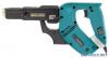 |


Facilidade de uso
V .......................volts n....................no load speed ° A ....................... amperes ....................Class II Construction Hz ..................... hertz .../min................revolutions or reciprocation per minute ................ alternating current FUNCTIONAL DESCRIPTION 002629 1 2 1. Lock button 2. Switch trigger 002636 1 1. Reversing switch 002648 1 1. Hook CAUTION: • Always be sure that the tool is switched off and unplugged before adjusting or checking function on the tool. Switch action CAUTION: • Before plugging in the tool, always check to see that the switch trigger actuates properly and returns to the “OFF” position when released. To start the tool, simply pull the switch trigger. Release the switch trigger to stop. For continuous operation, pull the switch trigger and then push in the lock button. To stop the tool from the locked position, pull the switch trigger fully, then release it. Reversing switch action This tool has a reversing switch to change the direction of rotation. Press the upper side (FWD side) of the reversing switch for clockwise rotation or the lower side (REV side) of the reversing switch for counterclockwise rotation. CAUTION: • Always check the direction of rotation before operation. • Use the reversing switch only after the tool comes to a complete stop. Changing the direction of rotation before the tool stops may damage the tool. Hook The hook is convenient for hooking the tool to your belt. It can be installed on either side of the tool. To remove it, pull it out in the direction of the arrow while raising. To install the hook, push it down until it “clicks” into place on the tool. ASSEMBLY 1 2 1. Casing 2. Thumb screw 12 3 1. Dust cover 2. Plane bearing 3. Bit 1 2 3 4 1. Lever 2. Stopper base 3. Plate 4. Casing CAUTION: • Always be sure that the tool is switched off and unplugged before carrying out any work on the tool. Installing or removing the bit 002656 Loosen the thumb screws which secure the casing. Pull out the casing in the direction of the arrow. 002657 Press the dust cover toward the plain bearing and pull out the bit. If the dust cover cannot be moved as far as the plain bearing, try it again after turning the bit slightly. To install the bit, insert it into the socket while turning it slightly. After installing, always make sure that the bit is securely held in place by trying to pull it out. 002663 Setting for desired screw length There are 3 (for Model 6833) or 5 (for Model 6834) positive- lock screw length settings. To obtain the desired setting, pull out the stopper base while depressing the lever until you see the number of the desired screw length (indicated on the plate) appear to rest on the very top edge of the casing. See the table below for the relation between the number indicated on the plate and the respective screw length ranges. Number indicated on the plate Screw length range 25/28 25 mm (1”) - 28 mm (1 - 1/8") 32 28 mm (1 - 1/8”) - 35 mm (1 - 3/8”) 40 35 mm (1 - 3/8”) - 41 mm (1 - 5/8”) * 51 41 mm (1 - 5/8”) - 51 mm (2”) * 57 51 mm (2”) - 57 mm (2 - 1/4”) (Note) * for Model 6834 only 1. Stopper plate 2. Casing 3. Adjusting knob A B 1 2 3 5mm (3/16") 1 2 3 1 002667 1. Stopper plate 2. Casing 3. Adjusting knob A B 1 2 3 5mm (3/16") 1 2 3 1 002667 1. Driving position 002665 Adjusting the driving depth Depress the stopper base as far as it will go. While keeping it in this position, turn the adjusting knob until the bit tip projects approx. 5 mm (3/16”) from the stopper base. Drive a trial screw. If the screw head projects above the surface of the workpiece, turn the adjusting knob in the A direction; if the screw head is counter-sunk, turn the adjusting knob in the B direction. 002666 Installing screw strip Insert the screw strip through the screw guide. Then insert it through the feeder box until the first screw reaches the position next to the driving position. Removing screw strip To remove the screw strip, just pull it out in the direction of the arrow. If you depress the reverse button, you can pull out the screw strip in the reverse direction of the arrow. 002669 1. Reverse button 1 1 002671 Extension handle (optional accessory) Use of extension handle allows you to drive screws into floors while standing. 1. Extension handle OPERATION 002676 001887 2 15mm(5/8") 1 1. Stopper base 2. Wall MAINTENANCE 001145 1 1. Limit mark Driving operation Switch on the tool by pressing the switch trigger and at the same time pushing the lock button. Hold the tool squarely against the workpiece and apply forward pressure to the tool. The screw will be automatically carried to the driving position and driven into the workpiece. NOTE: • Do not fire the tool without screws. This will damage the workpiece. • If the feeder box becomes sluggish in operation, spray car wax (spray type wax) on its sliding surfaces. Never lubricate it. Driving in corner This tool can be used to drive at a position 15 mm (5/8”) away from the wall as shown ...
Este manual também é adequado para os modelos :Brocas e shuropopverty - 6834 (134.04 kb)