


Assessments - 1, GPA: 4
(

 )
)
|
Fotos e especificações Sony MHC-S3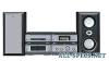 |


Facilidade de uso
20 Selecting a sound field ........................ 20 Understanding the multi channel surround displays .......................... 22 Customizing sound fields .................... 22 Other Features Changing the spectrum analyzer display ........................................... 26 To adjust the brightness of the display ..................................... 26 Falling asleep to music — Sleep Timer .............................. 26 Waking up to music — Daily Timer .............................. 26 Hooking Up the Optional Components Connecting audio components ............ 28 Additional Information Precautions .......................................... 29 Troubleshooting................................... 30 Specifications ...................................... 32 Table for the settings using SUR, EQ, and SET UP buttons ...................... 34 Adjustable parameters for each sound field ............................................... 35 * European model only. Parts Identification Parts Identification The items are arranged in alphabetical order. Refer to the pages indicated in parentheses ( ) for details. Main unit A/V amplifier 1 234567 89 Pop qgqfqdqsqaq; Tuner qh qjqk ql w; – – + + whwgwfwdwswa DIGITAL 9 (28, 32) ENTER/O/o/P/p2 (9, 12, 18, 19, 22–27) EQ qa (24) EQ ON/OFF qs (9, 24) FILE SELECT q; (20, 24) FUNCTION 8 (9, 11, 12, 17, 18, 28) GROOVE 5 (20) MOVIE MODE 4 (20, 21) MULTI CHANNEL DECODING indicator 6 (22) MUSIC MODE 3 (20, 21) PHONES jack qg SET UP qd (23–26) SUR qf (22) VOLUME 7 @/1 (power) 1 (8, 9, 32) CLOCK/TIMER wg (9, 18, 26) DISPLAY qh (10, 13, 15, 26, 32) ENTER w; (14, 15) IR receptor wh PRESET +/– ws (14, 15) PTY wa (15) STEREO/MONO qj (14) TIMER SELECT wf (19, 27) TUNER/BAND wd (14) TUNER MEMORY qk (14) TUNING +/– ql (14) CD player wjwkwl e;ea m . H > 1 2 3 efegehejek es ed Cassette deck hHAUTO REVERSE hHAUTO REVERSE > m H . h M > m H . h x A A el th r; tg tf ra rs td rd ts ta rf t;rl rkrjrhrg DISC 1–3 ek (11, 12, 18) DISC 1–3 indicators ej DISC 1–3 Z (eject) wl (11) PLAY MODE wj (11, 12, 18) REPEAT wk (11) N (play) eh (11, 12) X (pause) eg (11) x (stop) ef (11, 17) . (go back) ed (11, 12, 18) > (go forward) es (11, 12, 18) m (rewind) e; (11) M (fast forward) ea (11) CD SYNC rh (17, 18) DIRECTION t; (16–18) DOLBY NR rl (16–18) EDIT rk (18) HI-DUB rj (17) REC PAUSE/START rg (17, 18) – Deck A – N (forward play) tf (16) n (reverse play) td (16) x (stop) ts (16) M/> (fast forward/go forward) th (16) m/. (rewind/go back) tg (16) Z (eject) ta (16) – Deck B – N (forward play) ra (16, 17) n (reverse play) rs (16, 17) x (stop) rd (16, 17) M/> (fast forward/go forward) el (16) m/. (rewind/go back) r; (16) Z (eject) rf (16) Parts Identification hH H hH OoPpMm >. hH H hH OoPpMm >. Remote Control CD H wk (11, 12) CHECK 3 (12) CLEAR 4 (12) CLOCK/TIMER SELECT qg (19, 27) CLOCK/TIMER SET qh (9, 18, 26) DBFB qd (20) DISPLAY qk (10, 13, 15, 26, 32) D.SKIP 2 (11) ENTER wa (9, 12, 14, 15, 18, 19, 22–27) EQ qa (24) EQ ON/OFF qs (9, 24) 1 wk 2 wj 3 wh 4 wg 5 wf 6 wd 7 ws 8 wa 9 0 w; qa ql qs qk qd qj qh qf qg FUNCTION w; (9, 11, 12, 17, 18, 28) GROOVE qj (20) SET UP q; (23–26) SLEEP 5 (26) SUR ql (22) TAPE A hH wj (16) TAPE B hH wh (16, 17) TUNER/BAND wg (14) TUNING + 7 (14) TUNING – ws (14) VOL +/– qf BUTTON DESCRIPTIONS @/1 (power) 1 X (pause) 8 x (stop) 6 . (go back) wf > (go forward) wd m (rewind) ws M (fast forward) 7 O/o/P/p9 Getting Started Getting Started Hooking up the system Do the following procedure 1 to 5 to hook up your system using the supplied cords and accessories. Before connecting, place the system as described below. AM loop antenna FM antenna Cassette deck Tuner CD player A/V amplifier 2A2B2C2D14532E 3 3 Front speaker Front speaker (Right) (Left) continued Getting Hooking up the system (continued) 3 Connect the front speakers. Connect the speaker cords to the FRONT SPEAKER jacks. 1 Connect the CD player and the tuner Insert only the stripped portion. with the optical cable. Connect from the OPTICAL OUT jack on the CD player to the OPTICAL IN jack on the tuner. 1 Remove the cover of the jack. Red/Solid (3) – R L + OPTICAL IN FROM CDP-S3 Black/Stripe (#) 4 Connect the FM/AM antennas. Set up the AM loop antenna, then connect it. 2 Connect the optical cable. FM75./COAXIAL AMAM loop antenna OPTICAL IN FROM CDP-S3 2 Connect the flat system control cables to the SYSTEM CONTROL connectors until it clicks. Connect to the same colored jack in the order indicated on the rear panel. A SYSTEM CONTROL 1 (Red) Connect from the tuner to the A/V amplifier. B SYSTEM CONTROL 2 (Blue) Connect from the tuner to the A/V amplifier. C SYSTEM CONTROL 3 (Black) Connect from the CD player to the tuner. D SYSTEM CONTROL 4 (Black) Connect from the tuner to the cassette deck. E SYSTEM CONTROL 5 (White) Connect from the cassette deck to the CD player. To disconnect Extend the FM lead antenna horizontally. 5 Connect the power cord to a wall outlet. The demonstration appears in the display. When you press ?/1, the sys...