


Assessments - 2, GPA: 4.5
(

 )
)
|
Fotos e especificações Roland FA-66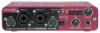 |


Facilidade de uso
Use only the supplied AC adaptor. ¦ FireWire (IEEE 1394) cables (one 6-pin - 6-pin cable, one 6-pin - 4-pin cable) Use one of these cables to connect the FA-66 to the IEEE 1394 connector (FireWire connector, iLink connector, DV connector) of your computer. The 6-pin - 4-pin cable cannot supply bus power. * Use only the FireWire (IEEE 1394) cables. If the supplied FireWire (IEEE 1394) cable becomes damaged or lost and you need a replacement, please contact the nearest Roland Service Center, or an authorized Roland distributor, as listed on the “Information” page. ¦ Owner’s manual This is the manual you are reading. Please keep it at hand for reference. ¦ CD-ROM This contains Windows drivers for the FA-66 and demo songs. * Be careful not to touch or scratch the recorded surface (unprinted surface) of the disc. Doing so may render the disc unreadable. If the disc gets dirty, use a commercially available CD cleaner to clean it. Do not play back the CD-ROM in a conventional audio CD player. Doing so may produce high-volume sound that can damage your hearing and/or speakers. Contents of the package Contents of the package An external amp, speakers, headphones, and mic are not included The external amp, speakers, or headphones you’ll need to hear the sound output from the FA-66 and the cables you’ll need to connect these items are not included. Nor is a mic included, which you will need to connect to the FA-66 in order to input audio. You will need to obtain these items yourself. An MD or DAT recorder and digital input/output cables are not included You can use an MD or DAT digital recorder to record, but the cables needed to connect these devices to the FA-66 are not included. You will need to obtain these items yourself. TRS phone plugPhone plug TRS phone plugPhone plug Front and rear panel Front panel 2 7 8 11 13 1 4 95 6 10 123 1. Combo input jacks These are analog audio input jacks with mic preamps. They accommodate either XLR or phone plugs, allowing you to connect a variety of equipment. Either balanced or unbalanced XLR plug signals may be connected. Phantom power (48 V) is provided for XLR type connections, allowing you to connect condenser mics that require phantom (unbalanced) (balanced) power. In this case, turn on the phantom power switch (19) located on the rear panel. * This instrument is equipped with balanced (XLR/TRS) type input jacks. Wiring diagrams for these jacks are shown on the right. Make connections after first checking the wiring diagrams of other equipment you intend to connect. 1:GND 2:HOT 3:COLD GND(SLEEVE) HOT(TIP) COLD(RING) 2. Input sensitivity knobs These adjust the input level of the signals input to the front panel combo input jacks (1). 3. Input impedance select switch This switch selects either high impedance (Hi-Z) or low impedance (Lo-Z) as the type of device connected to the INPUT 2 phone jack of the combo input jacks (1). If you have connected a guitar or bass to this jack, select the high impedance (Hi-Z) setting; if you have connected a mic, select the low impedance (Lo-Z) setting. * Combo input jack INPUT 1 is fixed at low impedance (Lo-Z). Front and rear panel Front and rear panel . Peak/Limiter indicator This indicates whether the signal being input via the combo input jacks (1) is distorting, or whether the limiter is operating. Limiter on The indicator will function as a limiter indicator. When the input signal exceeds a certain level, the limiter will operate and the indicator will light green. Limiter off The indicator will function as a peak indicator. Use the input sensi Limiter switch Status tivity knobs for each input jack to adjust the input level so that the peak indicator does not light red. The red LED will light if the sound distorts. 5. Power indicator Lights when the power is on. 6. Output indicator This will light green if signals are being sent from the computer’s audio output ports 1 and 2 (OUT 1/2). (see block diagram . front cover) 7. Digital input switch If you want to record a digital input, turn this on ( pressed inward). This lets the FA-66 synchronize to an external digital device connected to the digital input connector (25) 8. Sync indicator When the digital input switch (7) is on, this indicator shows the status of synchronization with a digital device connected to the digital input connector (25). (external synchronization mode) Lit Synchronized correctly. Blinking Not synchronized. Check that your digital device is correctly connected to the digital input connector. Also make sure that the connected digital device is set to the same sam- pling frequency as that selected by the FA-66’s sample rate select switch (18). 2 7 8 11 13 1 4 95 6 10 123 9. STEREO/MONO select switch (direct monitor section) This selects whether the input signal is to be monitored in stereo (STEREO) or in monaural (MONO). Turn this on ( pressed inward) if you want to monitor in monaural. For example, if you’ve connected a guitar only to INPUT 2/R, you would use the m...