


Assessments - 3, GPA: 3.7
(

 )
)
|
Fotos e especificações Smooth Fitness 5.45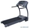 |


Facilidade de uso
A. Place the front handle bar (201) on top of the left and right upright (301). B. Secure left side with one O8 washer (812) and M8x45 mm Allen bolt (805) in the forward most hole . C. Secure right side with one O8 washer (812) and M8x45 mm Allen bolt (805) in the forward most hole . D. Connect pulse wire (217) and wire (111) on left and right side (as shown in diagram) . Then insert the remaining length of the wire into the front handle bar tube . Tighten all bolts with Allen Wrench . 805 X2 812 X2 301 201 805 111 217 805 812 812 301 21 5.45 MOTORIZED TREADMILL ASSEMBLY STEP4: Assemble The Side Handlebars NOTE: Side rails are interchangeable for use on both right and left sides A. Attach one handlebar (202) to the left upright (301) B. Secure the Side Handlebar with one M8 x75 mm bolt (845) and one O8 washer (812),through the top of front handle bar into the side handle bar . C. Insert two M8x18 mm (810) and two O8 washer (812) through the side handrail plate and thread into the upright . D. Repeat the above process for the right side . E. Tighten all bolts with Allen Wrench . 810 X4 845 X2 812 X6 845 812 810 202 845 812 812 301 810 301 202 812 5.45 MOTORIZED TREADMILL 22 ASSEMBLY STEP5: Assemble Computer Console A. Rotate the console until it stops as shown in diagram below . B. Tighten the screw (807) of the console connect tube (213) for right and left side . Console connect tube (213) will be adjust for the next steps of assembly . C. Attach the Handle Bar Cover . LR (208) to the underside of the console and the inside of the left upright (301), Secure with four M4.15mm screw (802). And secure with two M4.15mm screw (802) between the Handle Bar Cover . LR (208) outside and the console housing .upper. D. Attach the Handle Bar Cover . LL (207) to the top of the console and the outside of the Upright . Left (301).And secure with four M4.15mm screw (802). E. Repeat the above process for the right hand side cover (209) and cover (210) as shown in diagram. 802 X20 23 5.45 MOTORIZED TREADMILL ASSEMBLY STEP 6: Assembly base covers NOTE : Refer to folding instructions on page 27 . A. Fold up the running deck until it locks in place . B. Attach Upright Base Cover (302) to the outside of the Left Upright (301). Secure with two M4x15 mm screw (802). C. Attach Upright Base Cover (303) to the inside of the Left Upright (301). Secure with one M4x15 mm screw (802). D. Attach Upright Base Cover (305) to the outside of the Right Upright (301). Secure with three M4x15 mm screw (802). E. Attach Upright Base Cover (304) to the inside of the Right Upright (301). Secure with one M4x15 mm screw (802). 802 X7 5.45 MOTORIZED TREADMILL 24 ASSEMBLY STEP7: Attaching Rubber Cover Insert the rubber cover (306) into the slot upright base cover . 306 306 25 5.45 MOTORIZED TREADMILL ASSEMBLY STEP 8: Inserting Water Bottle Holders Attach the Water Bottle Holder(108)to the Console Housing . Upper(104)and push down until snap in place. 108 104 5.45 MOTORIZED TREADMILL 26 5.45 MOTORIZED TREADMILL 26 ASSEMBLY COMPLETE Assembly is now complete. Check that all the components are secure and all the hardware is tight . By this step all bolts and screws should be wrench tight. If any hardware is not wrench tight go back and tighten. The finished product should resemble the picture below. Safety Features Thesafetykeymustbeinsertedforthetreadmilltofunction.Thesafetykeytethershouldbewornatalltimeswhenthetreadmillisinuse.Thissafetyfeatureisdesignedtopreventinjury. There are two orange levers on this treadmill. The most forward lever is the folding lock which is used in folding and unfolding this treadmill. The other is used for transporting from one location to another 5.45 MOTORIZED TREADMILL 27 FOLDING INSTRUCTIONS How to fold up the treadmill: Your treadmill can be folded up for space saving storage. To do this follow the instructions here: Lift the deck from the rear towards the computer console. Listen for the click of the Folding Level locking mechanism . Be sure locking mechanism is engaged before transporting . (Transportation instruction on pg 29 ) 5.45 MOTORIZED TREADMILL 28 UNFOLDING INSTRUCTIONS How to unfold the treadmill: NOTE: To maintain stability make sure the rear transportation wheel is disengaged before unfolding treadmill To unfold the treadmill for use follow the instructions here: Release Lever Push the deck towards the computer console . Depress the Folding Level begin lowering the treadmill towards the floor release the folding level . Lower treadmill deck towards floor . 29 5.45 MOTORIZED TREADMILL TRANSPORT INSTRUCTIONS TRANSPORT INSTRUCTIONS: NOTE : Transport wheel must be down as picture below . To roll away for storage simply grab the rear deck, lift slightly and roll to desired location. Lift the deck from the rear so that the treadmill rests on the front transportation wheels and on the rear transportation wheel engages Roll to a desired location. 5.45 MOTORIZED TREADMILL 30 COMPUTER OPERATION A B C DEF START Button A...