


Assessments - 2, GPA: 5
(
 )
)
)
|
Fotos e especificações Spirit XE395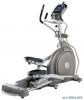 |


Facilidade de uso
Remove the tools first. Remove the hardware for each step as needed to avoid confusion.The numbers in the instructions that are in parenthesis (#) are the item number from the assembly drawing for reference. Assembly Tools #126. Phillips Head Screwdriver #125. Short Phillips Head Screw Driver #124. 13/14mm Wrench #129. 12/14mm Wrench XE395 Assembly STEP 1: Incline Rail & Console Mast 1. Slide the Incline Rail Assembly (2) into the U channel of the Main Frame (1). Be very careful not to damage the wires that exit each part. 2. Connect the Incline Rail Assembly (2) horizontally to the U channel of the Main Frame (1) with two Hex Head Bolts (77), two Flat Washers (96), and two Nyloc Nuts (89). Secure it vertically with four Hex Head Bolts (167), four split washers (178), four Flat Washers (100), and four star washers (179).Tighten using the wrenches provided (124 & 129). 3. Connect the Incline Motor wires (37 & 38) to the wiring harness & black wire that exits the Incline Rail Assembly (2). Push the excess cable inside the U channel. 4. Guide the twist tie that is attached to the Computer Cables (36 & 39) bundle through the Console Mast Cover (49) and the bottom of the Console Mast (12) until it exits the top of the steel tube Note: make sure the console mast cover is positioned like the illustration. Secure the Console Mast (12) by loosely threading two Hex Head Bolts (76) from the front and two Curved Washers (104) first.Then secure the mast from the side by loosely threading a Hex Head Bolt (75) and a Split Washer (128); Note: there is one bolt already installed in the receiving bracket that will engage with the slot at the bottom of the Console Mast.Tighten the bolt from the left side last. 5. Tighten the two front bolts first, then the side bolts with the wrench (124). Secure the Console Mast Cover (49) over the top of the plastic side covers (50 & 51). 6. Untie the twist tie, which is attached to the Computer Cables (36 & 39). Plug in the connectors of the two Hand pulse cables (44), Computer cable (36 & 39), Resistance cable (146), and Incline cable (146-1) in the bottom of the Console (32). Secure the Console (32) onto the mounting plate with four Phillips Head Screws (85).Tighten them with the Phillips Head Screw Driver (126). HARDWARE #96. 3/8” x 19 x 1.5T #100. 5/16” x 20 x 1.5T #104. 3/8” x 23 x 1.5T #128. 3/8” x 2T#85. M5 x 10mm Flat Washer Flat Washer Curved Washer Split WasherPhillips Head Screw (2 pcs) (4 pcs) (2 pcs) (1 pc) (4 pcs) #89. 3/8” x 7T #178. 5/16” x 1.5T #179. 5/16” #76. 3/8” x 3/4” Nyloc Nut Split Washer Star Washer Hex Head Bolt (2 pcs) (4 pcs) (4 pcs) (2 pcs) #77. 3/8” x 1-1/2” #167. 5/16” x 2-1/4” #75. 3/8” x 2-1/4” Hex Head Bolt Hex Head BoltHex Head Bolt (2 pcs) (4 pcs) (1 pc) 7 XE395 Elliptical Trainer XE395 Elliptical Trainer 8 1. Place two Wave Washers (103) onto the left and right Console Mast shafts; Slide the left (10) and right (11) swing arms onto the shafts and secure with two Hex Head Bolts (74) and two Flat Washers (99); tighten with the wrench (129). Note: make sure the arms are placed on their respective shafts as shown in the illustration. 2. Slide a grommet (145) onto the left cable (146-1); connect that cable to the cable (147) of the left swing arm (10); snap the grommet into the hole on the side of the console mast tube, then push the excess amount of cable through the grommet. Repeat this process on the right side, connecting cables (146 & 147). 3. Match the Front Handle Bar Cover (L) (68) with Rear Handle Bar Cover (L) (68-1) on left Swing Arm (10) and secure with three Sheet Metal Screws (107). Tighten using the Phillips Head Screw Driver (126). Repeat for the right Swing Arm (11), matching covers (69 & 69-1). HARDWARE STEP 2: Swing Arms #103. 17mm Wave Washer (4 pcs) #99. 5/6” x 23 x 1.5T Flat Washer (2 pcs) #107. 3.5 x 12mm Sheet Metal Screw (6 pcs) #74. 5/6” x 15mm Hex Head Bolt (2 pcs) #145. Grommet (2 pcs) 9 XE395 Elliptical Trainer 1. Untie the wire on the Rod End Bearing; connect the Swing Arm (L) (10) with Connecting Arm (L) (8) and secure with a Hex Head Bolt (79), Rod End Sleeve (22), a Flat Washer (100), and a Nyloc Nut (91). Tighten using the wrenches provided (124 & 129). 2. Repeat the process for the Right Connecting Arm (R) (9) and Right Swing Arm (R) (11). HARDWARE STEP 3: Connecting Arm #100. 5/16” x 20 x1.5T Flat Washer (2 pcs) #91. 5/16” x 7T Nyloc Nut (2 pcs) #79. 5/16” x 1-1/4” Hex Head Bolt ( 2 Pcs) STEP 4: Plastic Parts 1. Mate the Connecting Arm Covers (71 and 72) over the Left Connecting Arm (8) and secure with two Phillips Head Screws (82) and a Sheet Metal Screw (107).Tighten the screws using the Short Phillips Head Screw Driver (125). Repeat for the opposite side. 2. Install Roller Covers (64) onto each set of Rollers. Secure with four Phillips Head Screws (82).Tighten using the Phillips Head Screw Driver (126). 3. Attach the two covers (L-60) & (R-61) to the middle stabilizer tube (there is a sticker on the bottom side identify...